Fishing simulator with undumped game: King Fishing
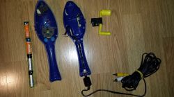
I got recently an interesting plug&play famiclone: fishing simulator with undumped game: King Fishing.
Shell
It contains four-direction volant joypad and four buttons:
* POWER,
* RESET,
* ESC (A button),
* START (B button).
![Image]()
![Image]()
//20240306_221859.jpg, 20240306_221921.jpg,
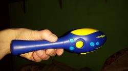
* And of course fishing reel (with ratched mechanism) that makes funny sound when turning (acts as START button).
![Image]()
//20240306_221957.jpg
* As it turned out after disassembling, there is also a small metal stripe with little weight attached that touches GND groundplane when shaking (responds as SELECT button)
![Image]()
//20240306_222108.jpg
* little DC motor
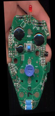
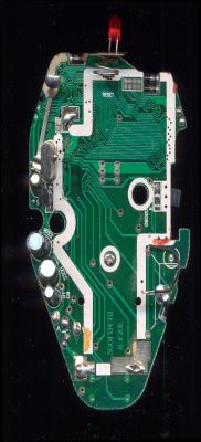
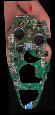
PCB
PCB contains 3 epoxy blobs:
![Image]()
![Image]()
![Image]()
//top_corr1.jpg, bottom_corr1.jpg, top_labels.jpg
Left one is Nes-on-chip, right one is PRG+CHR+mapper and bottom one is joypad parallel-to-serial decoder (UM6582).
Analysis
Full reverse enginering required patient analysis of all traces due to the white silkscreen that covers small portion of signals.
I tried to guess which tracks were responsible for what, but the Nes-On-Chip pinout does not seem to match UM6561 NOAC (which is present in 99% epoxy famiclones)
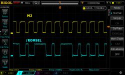
What I did instead was to first look which of the signals has M2 clock. After I found it, I searched for /ROMSEL - something that is HIGH when M2 is LOW and might be either LOW or HIGH when M2 is high:
![Image]()
//romsel.png
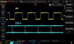
Next I probed some signals that were changing when M2 is low - probably CPU A, CPU R/W.
![Image]()
//cpu-a.png
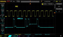
Next I probed some signals (8) that had 3 states (LO/HI/Z) and were not changing in respect to M2 - probably PPU D.
![Image]()
//ppu-dx.png
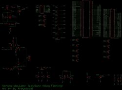
Looking at their positions with respect to the PRG+CHR+mapper blob it turned out this blob has the pinout almost identical to the 60pin FC connector (with some extra GND/VCC added in between). This quickly helped to identify all the tracks.
![Image]()
//sch.png
* PRG+CHR+mapper blob, in addition to common signals, has four mysterious jumpers (JP2A, JP2B, JP2C, JP2D), all opened.
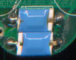
* NOAC has extra five mysterious jumpers (JP3A, JP3B, JP3C, JP3D, JP3E), motor control signal and two signals (I called them RX1, RX2), wired to something in blue heatsink, I cannot identify (X/Y sensors?)
![Image]()
//blue.jpg
Dumping
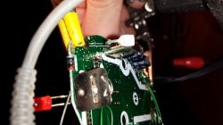
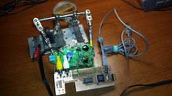
I used the good-trusted-dumping tool from my previous project (viewtopic.php?t=24758). Unfortunatelly here I got to solder about 20 wires to the tiny traces, carefully removing soldermask, but it worked flawlessly.
![Image]()
//20240306_222053.jpg
After reading CPU $8000-$FFFF and PPU address space, game turned out to use MMC3 code. Full 512kB PRG + 256kB CHR dump confirmed that PRG=128kB and CHR=256kB.
![Image]()
//scr.png
After a quick look at the game debugging:
* OUT2 (WR @ $4016.2) seems to control DC motor (0=off, 1=on)
* Game constantly reads $4017 - it suggests those RX1 and RX2 blue things are connected to this port.
I got recently an interesting plug&play famiclone: fishing simulator with undumped game: King Fishing.
Shell
It contains four-direction volant joypad and four buttons:
* POWER,
* RESET,
* ESC (A button),
* START (B button).
//20240306_221859.jpg, 20240306_221921.jpg,
* And of course fishing reel (with ratched mechanism) that makes funny sound when turning (acts as START button).

//20240306_221957.jpg
* As it turned out after disassembling, there is also a small metal stripe with little weight attached that touches GND groundplane when shaking (responds as SELECT button)
//20240306_222108.jpg
* little DC motor
PCB
PCB contains 3 epoxy blobs:
//top_corr1.jpg, bottom_corr1.jpg, top_labels.jpg
Left one is Nes-on-chip, right one is PRG+CHR+mapper and bottom one is joypad parallel-to-serial decoder (UM6582).
Analysis
Full reverse enginering required patient analysis of all traces due to the white silkscreen that covers small portion of signals.
I tried to guess which tracks were responsible for what, but the Nes-On-Chip pinout does not seem to match UM6561 NOAC (which is present in 99% epoxy famiclones)
What I did instead was to first look which of the signals has M2 clock. After I found it, I searched for /ROMSEL - something that is HIGH when M2 is LOW and might be either LOW or HIGH when M2 is high:
//romsel.png
Next I probed some signals that were changing when M2 is low - probably CPU A, CPU R/W.
//cpu-a.png
Next I probed some signals (8) that had 3 states (LO/HI/Z) and were not changing in respect to M2 - probably PPU D.
//ppu-dx.png
Looking at their positions with respect to the PRG+CHR+mapper blob it turned out this blob has the pinout almost identical to the 60pin FC connector (with some extra GND/VCC added in between). This quickly helped to identify all the tracks.
//sch.png
* PRG+CHR+mapper blob, in addition to common signals, has four mysterious jumpers (JP2A, JP2B, JP2C, JP2D), all opened.
* NOAC has extra five mysterious jumpers (JP3A, JP3B, JP3C, JP3D, JP3E), motor control signal and two signals (I called them RX1, RX2), wired to something in blue heatsink, I cannot identify (X/Y sensors?)
//blue.jpg
Dumping
I used the good-trusted-dumping tool from my previous project (viewtopic.php?t=24758). Unfortunatelly here I got to solder about 20 wires to the tiny traces, carefully removing soldermask, but it worked flawlessly.
//20240306_222053.jpg
After reading CPU $8000-$FFFF and PPU address space, game turned out to use MMC3 code. Full 512kB PRG + 256kB CHR dump confirmed that PRG=128kB and CHR=256kB.

//scr.png
After a quick look at the game debugging:
* OUT2 (WR @ $4016.2) seems to control DC motor (0=off, 1=on)
* Game constantly reads $4017 - it suggests those RX1 and RX2 blue things are connected to this port.
Statistics: Posted by krzysiobal — Wed Mar 06, 2024 3:00 pm — Replies 1 — Views 166